
Per-side control
Choose only the edges the part needs.
Each component exposes L1, L2, W1 and W2 separately, allowing different visible and unfinished sides.
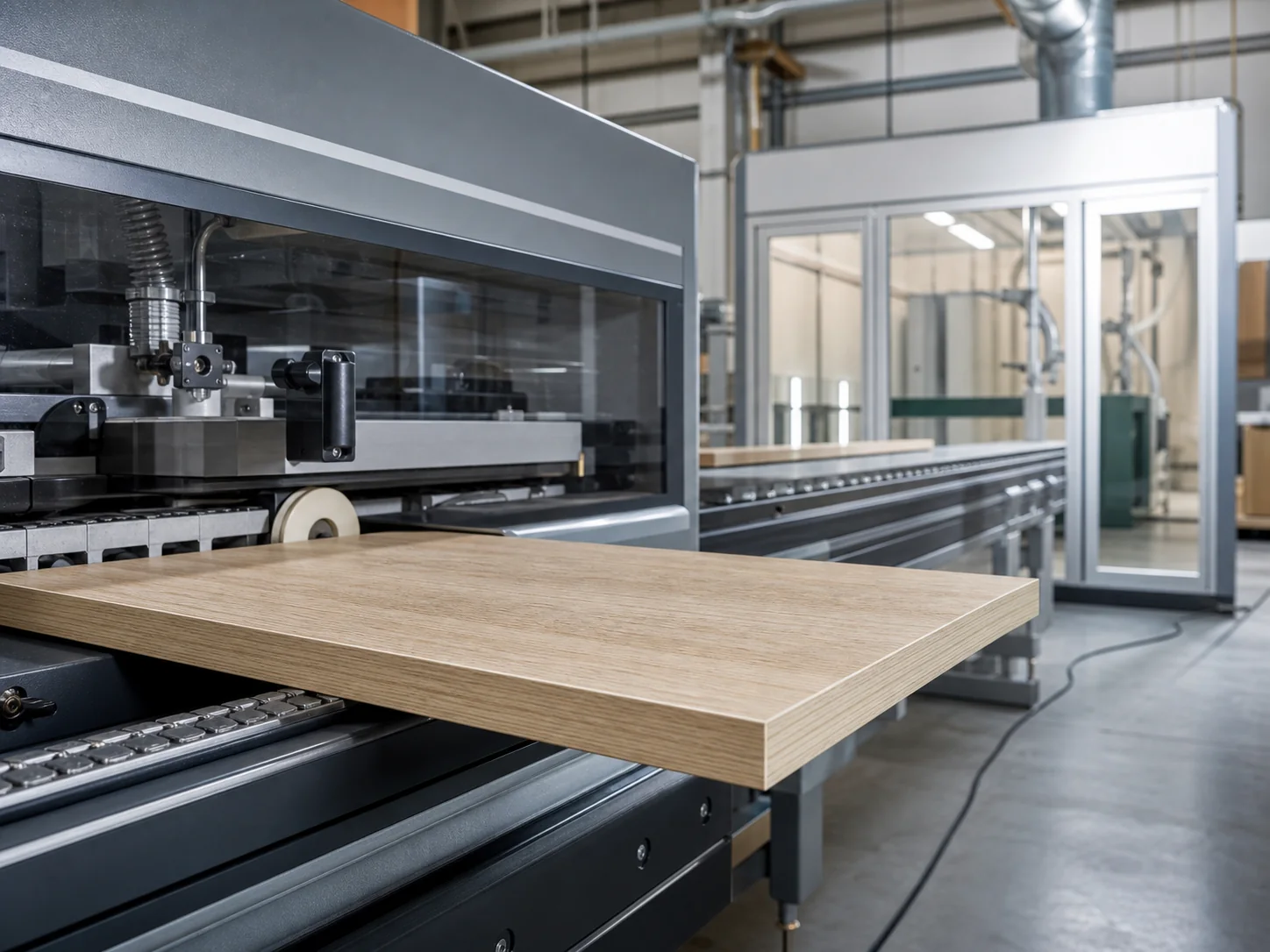
Edge banding
Apply compatible edging independently to the two length edges and two width edges of each component.
Attention to the edges
Per-edge specification removes ambiguity about which sides are visible. Compatible edge choices remain attached to the component throughout review.
Per-side control
Each component exposes L1, L2, W1 and W2 separately, allowing different visible and unfinished sides.
Compatibility
Available edging is constrained by material and thickness rather than offered as an unrelated finish.
Orientation
Part names, dimensions, grain and edge positions belong together. Supported selections stay with the cut list; unresolved orientation or matching questions require review before release.
Four sides, one orientation
L1 and L2 run along the component length; W1 and W2 run along its width. Keep their orientation tied to the finished dimensions and part reference. Visible-edge intent is separate from the exact tape selected after the board and thickness are known.
Read the panel consistently
Edge positions are interpreted with the component dimensions and orientation, so the same naming convention can be reviewed across every part.
These identify the two edges running along the component length.
These identify the two edges running along the component width.
The available edge articles are constrained by the selected board and thickness before review.
Edge review
A useful edge instruction identifies the part, its orientation and the exact exposed sides.
Open Board CuttingConfirm the component name and dimensions
○Orient length and width consistently
○Identify each visible or deliberately unfinished side
○Select only compatible published edging
○Review grain and edge positions together
○Before you begin
The practical details, so you can take the next step with confidence.
Yes. L1, L2, W1 and W2 are selected separately for every component.
Those words can change with installation orientation. Length- and width-edge labels remain tied to the entered component geometry.
No. Available choices are constrained by the selected material and thickness.
Add edging
The cutting workspace will show compatible edge choices for each component.